IMC-2001

IMC-2001

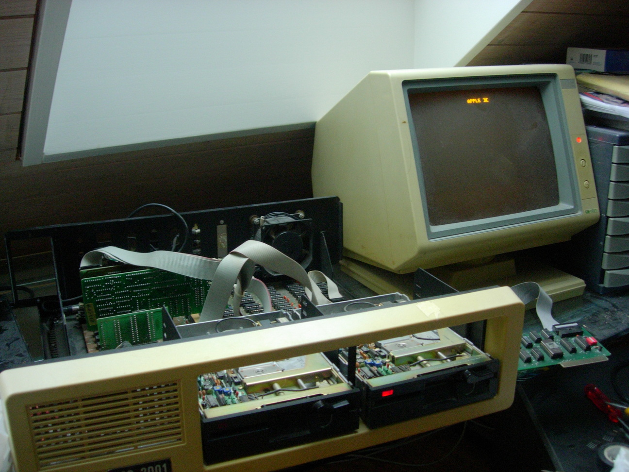
This is an old Taiwanese Apple ][ / CP/M clone.

Status

Trying to fix several issues:

  • power switch makes some hissing noises
  • the lever moving the contacts between 40-character and 80-character mode for the CRT output is corroded, doesn’t always make contact and produces a flickering image
  • keyboard cable is broken, at least the data line
  • the paddle and the joystick connectors miss some legs for putting them into the sockets on the motherboard
  • sometimes I get into the monitor
  • lower-nibble bit 3 of the key being pressed is missing, unclear where it is lost, I suspect a bad register on the motherboard holding the current ASCII value of the key pressed or something similar. Replaced a bad 74LS257N, works now just fine.
  • ROM 1 with BASIC is broken (and gets really hot). This explains the booting issues.. (will be tricky to get a replacement)
  • possibly much more

Known things to work

  • The keyboard works electronically (8039 MCS-48 like CPU with a 2K EPROM)
  • the Rockwell R6502 CPU has a phase 0 clock and seems to go through address lines and output data (another strong indicator is the ‘Apple ][’ sign on the monitor when switching on which indicates 6502, 40-character ROM, video circuit seems to be just fine).
  • Monitor is working just fine (which is sort of amazing for such an old CRT monitor).
  • I can boot from a Apple ][ CP/M 56k floppy and I get a prompt, now as the keyboard works and the CP/M on the 80-character card I can also assume the Z80 is working just fine.

Images

From the outside:

IMC-2001

Booting into Apple ][ CP/M 56k:

IMC-2001

The motherboard and floppy drives:

IMC-2001

Keyboard layout:

keyboard layout

Keyboard has a 8039 CPU inside and a 2K EPROM:

PCB and controller

On the oscilloscope:

serial keyboard signal

Broken keyboard cable (the black pins are just connectors added by me to test connectivity, both connector are female per default):

PCB and controller

Documentation

This is the “Operation Manual for IMC-2001, version 2.01”:

manual frontpage

The complete scanned manual

Schematics

Power connector on the motherboard:

O O O O O O
| | | | | +--- GND   black
| | | | +----- +12V  red
| | | +------- -5V   blue
| | +--------- -12V  brown
| +----------- +5V   white
+------------- +5V   white

keyboard cable connectors:

connector to machine (sort of a gummy version of a DB-9):

computer has a 9-pin DSUB connector male:

  +-----------    white  INTR
  | +---------    black  GND
  | | +-------    green  DATA
  | | | +-----    blue   RESET
  | | | | +---    Yellow CLOCK
-------------
\ O O O O O /
 \ O O O O /
  ---------
   | | | +----    red    5V
   | | +------    n.c.
   | +--------    n.c.
   +----------    n.c.

On the keyboard PCB there is a strange white connector with the following layout:

    +------------- white   INTR (active low, after last clock tick)
    | +----------- black   GND
    | | +--------- blue    RESET (active low)
    | | | +------- green   DATA
    | | | | +----- yellow  CLOCK
    | | | | | +--- red     +5V
   +-----------+
   |o o o o o o|
   +-----------+
   |           |

Links